Shell and Tube Heat Exchangers are the most used kind of exchangers to transfer heat between two fluids. A shell and tube heat exchanger consists of a shell (a large pressure vessel) with a bundle of tubes inside it. One fluid runs inside the tubes, and another fluid flows over the outside of the tubes (through the shell) to transfer heat through the tube walls.
The assembly of tubes is called a tube bundle since the tubes are bundled together by tube sheet(s) and baffles to fit in the shell. Most heat exchangers use pain tubes, but low-fin tubes may also be used inside a shell.
Shell And Tube Heat Exchangers Configurations
There can be many variations in shell and tube heat exchanger designs. Typically, all the tube ends are connected to holes in tube sheets. The tubes may be straight and have tube sheets on each end or bent in a U shape, called U-tubes, to connect to only one tube sheet.
In nuclear power plants with pressurized water reactors, huge heat exchangers, such as steam generators and feedwater heaters, are mostly shell and tube heat exchangers, typically with U-tubes, while even bigger steam condensers employ mostly straight tubes.
Detailed configuration, designation, and terminology of shell and tube heat exchangers are described in the TEMA Standards by the Tubular Exchanger Manufacturers Association, Inc. (TEMA).
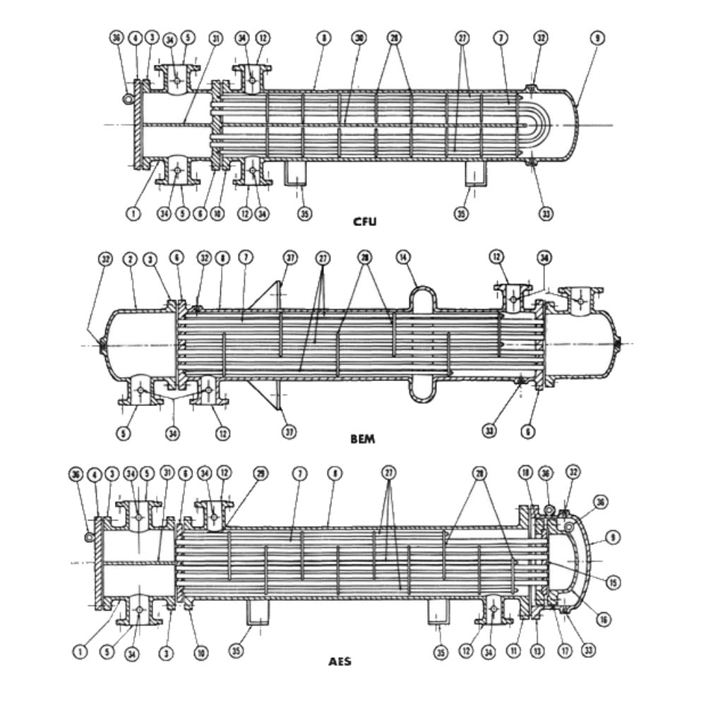
Three example TEMA heat exchangers are shown in this image with labeled names listed in the following table. TEAM uses 3 letters to designate a heat exchanger configuration, the first letter is for the front head (the one that is connected with the tube side flow), the second letter is for the shell, and the third letter is for the rear head.
U-tubes and round heads are the most simple and commonly used configurations, while straight tube constructions are desired when cleaning is needed.
Shell and Tube Heat Exchanger Terminology

| 1 | Stationary (Front) Head Channel | 20 | Slip-on Backing Flange |
| 2 | Stationary (Front) Head Bonnet | 21 | Floating Tubesheet Skirt |
| 3 | Stationary (Front) Head Flange | 22 | Floating Tubesheet Skirt |
| 4 | Channel Cover | 23 | Packing Box Flange |
| 5 | Stationary Head Nozzle | 24 | Packing |
| 6 | Stationary Tubesheet | 25 | Packing Follower Ring |
| 7 | Tubes | 26 | Lantern Ring |
| 8 | Shell | 27 | Tie Rods and Spacers |
| 9 | Shell Cover | 28 | Transverse Baffles or Support Plates |
| 10 | Shell Flange Stationary Head End | 29 | Impingement Baffle or Plate |
| 11 | Shell Flange Rear Head End | 30 | Longitudinal Baffle |
| 12 | Shell Nozzle | 31 | Pass Partition |
| 13 | Shell Cover Flange | 32 | Vent Connection |
| 14 | Expansion Joint | 33 | Drain Connection |
| 15 | Floating Tubesheet | 34 | Instrument Connection |
| 16 | Floating Head Cover | 35 | Support Saddle |
| 17 | Floating Head Flange | 36 | Lifting Lug |
| 18 | Floating Head Backing Device | 37 | Support Bracket |
| 19 | Split Shear Ring |
Advantages
In comparison with plate heat exchangers, tubes can hold much higher pressure. Because less gasket area is used, shell and tube heat exchanger can also handle higher temperatures than others.
Shell and Tube heat exchanger is also mostly used when the two fluids involved in heat transfer need to be well kept separated. Another big advantage of shell and tube heat exchangers is that they are often easy to service, particularly with models where the tube bundle can be easily pulled out, and tubes can be easily replaced or cleaned.
Disadvantages
Because shell and tube heat exchangers are mostly built with bare tubes or low-fin tubes, they are not efficient in heating or cooling gas with liquid, especially when the gas pressure is low.
Usually, more metals are used than other types of heat exchangers when transferring an equal amount of heat.
Applications
The simple design of a shell and tube heat exchanger makes it an ideal cooling solution for a wide variety of applications.
Industries using shell and tube heat exchangers include Food and Beverage, Marine Applications, Air Processing, Compressor Cooling, Cooling of hydraulic fluid and engine oils, Petrochemical Processing & Refining, Pharmaceuticals, Power Generation, Metals and Mining, Refrigeration, and Pulp & Paper.
Materials
To transfer heat well, the tube material should have good thermal conductivity. When heat is transferred from a hot fluid to a cold fluid through the tube walls, lower thermal conductivity can be the bottleneck.
The tube material should also be compatible with both the shell side and tube side fluids to minimize deterioration such as corrosion and fouling. Currently, available metals include copper alloy, stainless steel, carbon steel, Inconel, nickel, Hastelloy, and titanium.
A good choice of tube material is the optimization of price, conductivity, and durability. Shell materials and tube materials are further discussed in these two links.
Shell And Tube Heat Exchangers Cleaning and Testing
Because the internals of a shell and tube heat exchanger can be easily accessed, cleaning and testing can be conveniently conducted. Because solid in the fluid can accumulate in a heat exchanger, corrosion and vibration can gradually damage a heat exchanger. Cleaning and testing are periodically necessary to keep a heat exchanger healthy.
Eddy’s current tests are the most popular method to test tube pitting and leaking. Ultrasonic testing is used to test shell shining due to corrosion or flow accelerated erosion.
The nuclear regulations also require safety-related heat exchangers in nuclear power plants to be tested to ensure their thermal capacities. Hydraulic cleaning and testing are scheduled for some nuclear power plant heat exchangers in every refueling outage.
Shell And Tube Heat Exchangers Repair and Replacement
Almost every part of a shell and tube heat exchanger can generally be repaired or replaced cost-effectively. This includes the shell, channels, channel covers, tubes, tube sheets, baffles, tie-rods and spacers, seal strips, and other parts.
Shell and tube heat exchangers repair and replacement are mostly needed for copper tubes and carbon steel parts. Tube plugging is often used to stop singular tube leaks if the loss of the heat transfer surface can be tolerated. When plugging reaches the thermal capacity limit, the whole tube bundle can be replaced. If the tube sheet of a damaged tube bundle is still in good condition, it can be reused, and only the tubes are replaced – this is usually called re-tubing.


