The first step in troubleshooting your furnace is to understand how it works. The sequence of control, the safety interlocks and, in particular, what it is doing or not doing. If you had trouble with your furnace, this quick guide helps determine which course of action to take to bring your gas furnace to work again.
A Word of Caution
If you feel uncomfortable or in doubt about the furnace troubleshooting procedures outlined below, make a service call to your HVAC technician. Electricity and natural gas have no respect for anyone, and given the wrong series of events could be dangerous.
Remember, Furnaces provide heat due to controlled combustion. Uncontrolled combustion is undesirable and leads to a 911 call for fire department assistance. Therefore, it is recommended to read the entire article before you start any repair procedures.
How Does a Furnace Work
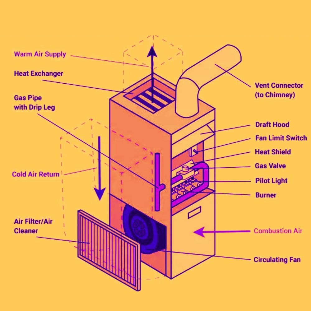
Furnaces work on the principle of forced air heating. The furnace transfers heat to the air, which blower fans then send it to the house. The main components of your furnace are the control system (thermostat and electrical controls), gas valve, burners, heat exchanger, blower, and duct and ventilation system.
Every furnace component must work together to keep you comfortable. Therefore, you may need to know some of the gas furnace components to better understand the process.
Furnace Components

There are many components that work together in a furnace. Here are the main basic components for almost any gas furnace.
- Heat Exchanger
- Pilot light
- Hot surface ignitor
- Gas valve
- Gas Burners
- Draft Inducer Motor
- Pressure switch
- Air filter
The Sequence of Control
The sequence of control is the logic that your furnace follows to successfully operate. Some of the events are electronic, and others are mechanical. It all starts and ends with the thermostat.
If all the processes are completed in the correct order and within specific time frames, the furnace will light off and keep your home warm and toasty. Every manufacturer has a sequence that is similar but could be different than what is described here.
The sequence is summarized as:
Call for heat – begin ignition process – ID fan on-command – ID fan proof – check combustion chamber temperature – HSI glows – gas valve open – ignition light-off – ignition proof – combustion chamber warm-up – blower fan energized – heat for the home – a thermostat is satisfied – gas valve closes – supply air fan operates till the limit switch de-energizes.
This is further described below.
The initial call for heat is made by the thermostat according to your indoor set point. Next, contacts within the thermostat close and energize the electrical circuit (24 volts) that leads to the furnace control board.
Essentially the thermostat commands the furnace by sending 24 volts of control voltage to the control board in the furnace. The control board is the printed circuit board with wires connected to it and possibly one or more LED lights. The control board begins the ignition process.
The first thing that happens is the induced fan motor is energized and sucks air from the combustion chamber, and blows it up the flue (pre-purge cycle). The control board then wants to “prove airflow”, so a small piece of flexible tubing (sometimes two) from the fan leads to a pressure switch diaphragm.
The diaphragm closes a set of contacts that allows the control voltage to continue back to the control board. Finally, the control voltage returns to the control board and “proves airflow” (which completes the control voltage circuit).
Other methods to prove airflow, such as a centrifugal switch that closes when the induced fan motor comes up to speed. This is indirect proof of airflow because it implies that airflow occurs since the fan shaft is spinning.
When proof of airflow is confirmed, the control board wants to know the combustion chamber is not overheated. A temperature limit switch measures the combustion chamber temperature (It also controls the supply air fan on/off settings).
If the temperature is too high, the limit switch does not allow the ignition sequence to proceed. However, suppose the temperature is not too high. In that case, the limit switch allows the control voltage to return to the control board, which acknowledges this safety is satisfied, and the ignition sequence continues.
Note that this limit switch can also be wired in series with the air-flow-proof described above. Either way, the control board must be satisfied with airflow through the combustion chamber, and the furnace is not overheated.
Assuming you do not have a standing pilot light to ignite the burners, the next event is to energize the hot surface igniter (or you may have a spark igniter). The hot surface igniter (HSI) will glow red or yellowish after 15 seconds. Because the control board allows an electric circuit to flow through it, much like the filament in a light bulb.
If you have a spark igniter, you will see (and probably hear) a continuous spark jumping from the two electrodes (think of a spark plug).
Shortly after the hot surface igniter begins to glow, the control board allows the gas valve to open. Gas will feed the burner, and the furnace lights off as the gas passes over the igniter. Normally you will hear the “swoosh” noise of the gaslighting and see flames entering your combustion chamber. Successful trial ignition.
Next, the flame sensor must “prove ignition” for trial ignition to continue. The flame sensor is just beyond the burner, directly in the burner’s flame and is often a bent-rod looking thing. It has wires leading back to the control board that confirms the burner is firing.
If the flame sensor does not “prove”, the control board will shut down the ignition sequence and leave the induced draft fan on (for about 30 seconds or so) to purge the combustion chamber. The control board will try for ignition 3 times or so before it goes into a hard lock-out.
At this point, some systems will wait for an hour or so before re-attempting trial ignition, and other systems may require a manual reset. It just depends on the manufacturer.
Assuming you have a successful ignition sequence, the temperature inside the heat exchanger will rise to a predetermined set point as determined by the temperature limit switch described above. The supply air fan will then be energized to blow warm air across the heat exchanger and into your ductwork distribution system when this set point is achieved.
When the thermostat is satisfied, the thermostat contacts open and the control voltage is not delivered to the control board. This stops the ignition sequence, and the gas valve is closed.
The supply air fan will continue to run for another minute or so, removing all the heat inside the heat exchanger. When the limit switch that measures furnace temperature hits its low limit setting, the supply air fan is de-energized, and the furnace is off.
The process is quite simple once you understand the sequence and realize that the controls are almost dummy-proof. It might even be best to observe your furnace during its ignition sequence.
On most furnaces, you can remove the access panel and watch. Just check to see if there is a rocker switch where you took the panel off. This will prevent ignition and needs to be taped closed when the cover is off.
Troubleshooting the Furnace
If your furnace does not light off properly or cycles during operation, check the items below. You can safely observe the furnace interior on most induced draft type furnaces. Forced draft type furnaces will probably require all covers in place to operate correctly.
Read your owner manual to determine the type you have. Also, check for rocker switches at the access panels. You may need to tape them closed while troubleshooting.
Observe the furnace sequence. Remove the access cover from the front of the furnace. Next, sit in front of your furnace and have someone turn the thermostat up to call for heat. This should start the ignition sequence. If nothing happens, begin troubleshooting the thermostat or the control voltage transformer.
Verify induced fan operation
This should happen immediately after the thermostat calls for heat. You will hear the fan start, so listen for any grinding or knocking noises related to the fan. You should hear just the air noise from the furnace blower fan operation.
If the fan starts and nothing else happens, it is probably because the control board cannot prove airflow. This points to a bad or plugged pressure switch or the attached tubing. Disconnect the tubing and see if there is water inside the tubing. If so, drain it and retry firing the unit.
The second option is that the temperature limit switch that measures furnace temperature is open and not allowing the ignition sequence to continue. You can jumper this out at the control board to simulate proper operation. If the unit lights off properly, replace the switch.
Verify hot surface igniter operation
This is just a visual confirmation that you see the glow of the igniter. If you have a spark furnace igniter, verify you can see and hear the spark.
Verify flame sensor operation
When a furnace lights off and immediately shuts down many times, it is due to a bad flame sensor. They are easy to remove and are generally held in place with a single screw and bracket. Disconnect the wiring, remove the flame sensor and clean it with steel wool or something similar.
Try not to remove the protective coating during cleaning and always have a spare. Also, check the ceramic base for cracks or discolour. Finally, reinstall the flame sensor and try for ignition again.
These are the most popular reasons why a furnace will not operate. Less popular reasons are listed below and discuss in other articles.
Check the air filters
Over time, the furnace filter can get dirty. Always make sure they are clean so you get the proper airflow across your heat exchanger. Clogged filters reduce the airflow and cause the combustion chamber to get too hot.
Bad roll out pressure switch
Suppose your flue was clogged or not allowing the induced draft fan to operate properly. In that case, the flame from the burner might not be directed inside your combustion chamber. Essentially the flame spills back inside the furnace’s cabinet and causes the rollout switch to stop the ignition sequence.
Though not high on the list of probable reasons, this is still worth mentioning. Check for a clogged flue or a soon-to-fail induced draft fan.
Properly secure the panel
Follow your manufacturer’s instructions for properly securing the furnace panel. Many furnaces will not operate if the panel is not pressed in all the way.
Low gas manifold pressure
This will require a manometer and a little knowledge about your gas valve. First, connect the manometer and check the pressure against what is recommended in your owner manual. Generally, low pressure means a new gas valve or debris in your pressure regulator.
Final Word
Here is the recap from the above furnace troubleshooting chart:
Check the thermostat
Verify induced fan operation
Verify hot surface igniter operation
Verify flame sensor operation
Check the air filters
Check the power switch
Check the gas pressure
Properly mount and fasten access panels
When troubleshooting your furnace doesn’t solve your issues, never hesitate to contact a qualified HVAC professional. The best way to keep your furnace running is to have your heating and cooling system inspected by an expert technician.
We hope this guide has helped you diagnose a furnace issue. We welcome your comments, leave a little knowledge for others.


