
Embarking on wiring a heat pump thermostat need not be a complex undertaking. With the right guide and a structured approach, what might appear intricate can be simplified. This article is crafted to demystify the process of heat pump thermostat installation, providing you with the necessary knowledge and steps to tackle the job confidently.
Mastering thermostat wiring, especially for heat pumps, offers many practical benefits. Despite common perceptions, it’s a manageable task requiring a systematic approach rather than expert-level electrical proficiency.
The variety of electronic thermostats on the market is extensive, with options for every preference and compatibility consideration. It is crucial to ensure that the thermostat you plan to install is suited to your heat pump system. A modern, programmable thermostat, which could be an affordable upgrade, may enhance both the functionality and the efficiency of your system.
In electronic thermostats within the U.S., the standard operating voltage is 24V AC, supplied by a 110V/24V transformer. This specification is a key factor in the installation process. It should be confirmed by referencing your thermostat’s manual, which provides specific instructions and safety guidelines.
When dealing with the wiring of a heat pump system, you will typically encounter at least eight wires that need to be correctly connected to ensure the system operates optimally. A practical tip is to take a clear photograph of your current thermostat’s wiring before any disconnection occurs. This image is an invaluable reference, aiding in the accurate reconnection of the new thermostat.
It’s important to note that while DIY projects can be fulfilling, electrical work should be approached with caution. If you’re not experienced with electrical systems, it’s advisable to enlist a professional technician. Safety is paramount, and qualified expertise is essential for tasks that involve electrical components.
DIY Step-by-Step Guide to Wiring Your Heat Pump Thermostat
Ready to take control of your home’s comfort? This DIY guide is your step-by-step roadmap to successfully wire a heat pump thermostat. Whether upgrading to a programmable model or replacing an old unit, these instructions will walk you through each stage of the wiring process with ease. Let’s get started on this empowering home improvement project.
Safety First!
Before initiating the process of wiring your heat pump thermostat, it is imperative to prioritize safety. Begin by ensuring that the electrical supply to your HVAC system is completely shut off. This can usually be done at the circuit breaker, which should be clearly labeled.
Once you believe the power has been turned off, take no chances. Use a multimeter to test and confirm that all power to the unit is indeed off. This step is crucial to avoid the danger of electrical shock. It’s not enough to switch off the thermostat or the HVAC system; the entire power supply must be disconnected for a safe working environment.
Tools and materials needed to wire a heat pump thermostat:
- Multimeter
- Screwdrivers (Phillips and flathead)
- Wire stripper
- Needle-nose pliers
- Thermostat Manual
- Digital camera or smartphone (for taking pictures)
- Tape or labels for marking wires
Step 1: Mounting the New Thermostat
Begin by detaching your old thermostat from its wall plate. Typically, thermostats can be pulled straight off the wall. Still, some models may require lifting from the bottom or releasing a locking tab.
Before proceeding with the removal, it’s crucial to take clear, detailed photographs of the existing wiring setup for future reference. Proceed to carefully label each wire, corresponding to its terminal connection on the old thermostat, to ensure accurate reattachment to the new unit.
Once the old unit is disconnected and the wires are labeled, you can mount the new thermostat. Make sure it’s properly leveled and firmly fixed to the wall to avoid any operational issues.
Step 2: Connecting the Wires
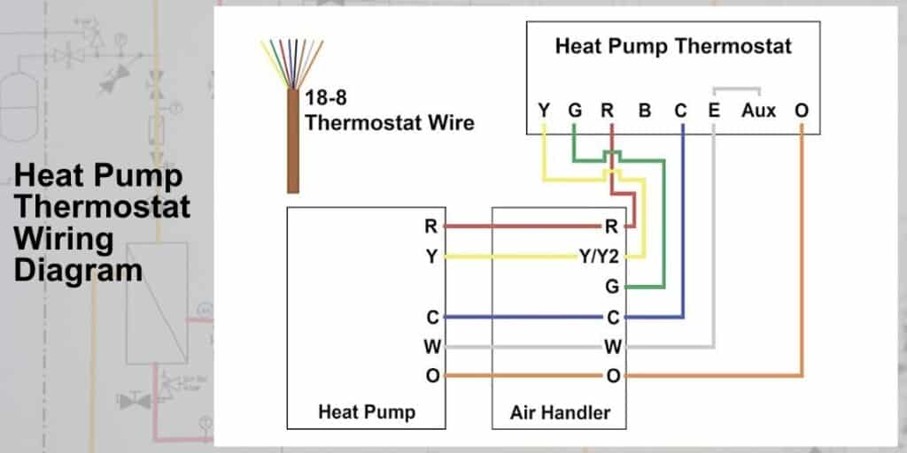
With the new thermostat securely in place, it’s time to connect the wires. Refer to the labels you created earlier to match each wire to its corresponding terminal on the new thermostat. Each wire has a designated terminal, typically marked with a letter that corresponds to the wire’s function as follows:
- R (Red wire): Connect to the R terminal for power.
- C (Blue/Black wire): Connect to the C terminal for constant power.
- Y (Yellow wire): Connect to the Y terminal to control the cooling function.
- G (Green wire): Connect to the G terminal to manage the fan.
- W (White wire): Connect to the W terminal for heating.
- O/B (Orange/Brown wire): Connect to the O/B terminal to control the heat pump’s reversing valve.
- Aux/E (Auxiliary/Emergency wire, color varies): Connect to the Aux/E terminal for auxiliary or emergency heating if applicable.
Ensure each connection is tight and secure.
For a comprehensive guide on which wire connects to which terminal, please refer to the dedicated ‘Thermostat Wiring Guide‘ section at the bottom of this article. This guide will provide detailed explanations, ensuring you make the correct connections for your HVAC system.
Step 3: Finalizing the Installation
After all wires are connected, fix the thermostat faceplate to the wall mount. Restore power to your HVAC system at the circuit breaker.
Follow the manufacturer’s instructions to configure the thermostat settings.
Step 4: Testing the System
Once the new thermostat is wired and in place, it’s time to put it to the test. Power up your HVAC system and cycle through each thermostat function—cooling, heating, and fan—to ensure everything operates as it should.
Should you encounter any hiccups during this process, don’t hesitate to refer to the troubleshooting section of your thermostat’s manual for guidance.
There you have it—a comprehensive guide to wiring your heat pump thermostat. By following these step-by-step instructions, you should be well on your way to regulating your home’s temperature with ease and precision.
Thermostat Wiring Guide
Understanding thermostat wiring is crucial for ensuring your HVAC system operates correctly. This guide provides an overview of connecting each wire to its corresponding terminal.
Color coding and terminals:
- W (White): Connects to the heating system.
- Y (Yellow): Attaches to the compressor and controls the cooling system.
- G (Green): Operates the fan.
- R (Red): Powers the thermostat, with Rh for heating and Rc for cooling, often connected by a jumper wire.
- C (Common or Black/Blue): Supplies continuous power to the thermostat for features like display and programming.
Before assuming the standard color coding, always check your existing wiring configuration. This is especially true if you have an older system or if you suspect the wiring has been altered in the past.
Standard Heat Pump Thermostat Wiring Procedure
Regardless of the level of sophistication of your thermostat — whether it’s a basic dial or a high-tech programmable model — the wiring principles are generally the same.
For a single-zone heat pump, the standard wiring connections are:
- Red wire to Rh or Rc: Provides power to the thermostat.
- Black or Blue wire to C: Offers a return path for electricity to maintain thermostat functions.
- White wire to W: Controls the heating relay.
- Yellow wire to Y: Manages the compressor relay for cooling.
- Green wire to G: Governs the fan relay.
- Orange wire to O: Activates the reversing valve for heating mode in a heat pump.
- Blue wire to B: This is also related to the reversing valve but for cooling mode.
- Y2, W2, X2: Serve second-stage heating and cooling and may come in various colors like brown, pink, gray, or tan.
Notes: Always verify the wiring based on the specific brand and model of your thermostat, as manufacturers like Nest, Honeywell, and others may have unique wiring requirements. Additionally, multi-stage systems and those with auxiliary functions will have a more complex wiring setup.
Remember, this guide serves as a general overview, and if there’s any uncertainty or your system doesn’t follow the standard color code, consulting with a professional is strongly advised.
In wrapping up, the key to successful heat pump thermostat installation lies in attention to detail and adherence to guidelines. Always consult the manufacturer’s documentation for your specific thermostat model, as it provides the authoritative roadmap for wire-to-terminal connections. If your wires deviate from the conventional color code, prioritize terminal labels over wire colors to navigate the wiring process accurately.
Remember, while a DIY endeavor can be fulfilling, precision and safety cannot be overstated. Should there be any hesitation or confusion, the expertise of a professional HVAC technician is invaluable. By combining thorough preparation, careful execution, and professional advice when needed, you’ll ensure your thermostat serves you effectively and safely for years to come.