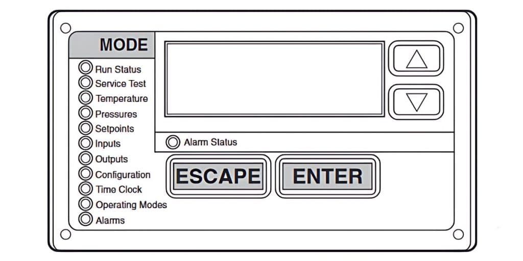
Knowing the Carrier ComfortLink alarm codes can be really helpful for figuring out and solving problems with your HVAC system. These codes show when something isn’t right and can cause either one part of the system or the whole thing to stop working. Each alarm has its own special code, and it’s important to understand these codes so you can keep your system running smoothly and reliably.
What is Carrier ComfortLink?
Carrier ComfortLink is an advanced control system designed for Carrier’s commercial HVAC (Heating, Ventilation, and Air Conditioning) equipment. This sophisticated technology provides comprehensive monitoring and control of HVAC units, ensuring optimal performance, energy efficiency, and reliability.
ComfortLink systems are commonly used in commercial buildings, such as offices, hospitals, schools, and other large facilities, where maintaining a controlled and comfortable indoor environment is crucial.
Key Features of Carrier ComfortLink
- Advanced Diagnostics and Alerts:
ComfortLink systems come equipped with detailed diagnostic capabilities that monitor the health and performance of HVAC units. The system can detect and report a wide range of issues through alarms and alerts, which help in early identification and resolution of potential problems. These alarms are coded and logged with time and date stamps, providing a historical record for maintenance and troubleshooting. - Energy Efficiency:
By using precise control algorithms and real-time monitoring, ComfortLink helps in optimizing energy usage. It adjusts HVAC operations based on the building’s requirements, reducing energy waste and lowering operational costs. This makes it an ideal choice for businesses looking to improve their energy efficiency and sustainability. - Remote Access and Control:
ComfortLink allows for remote monitoring and control of HVAC systems. Facility managers can access the system through web-based interfaces or mobile applications, enabling them to make adjustments, respond to alerts, and check system status from anywhere. This flexibility is particularly valuable for large or multi-site operations. - Integration Capabilities:
The system can integrate with other building management systems (BMS), providing a unified platform for managing various building functions. This integration capability enhances overall building efficiency by allowing coordinated control of HVAC, lighting, security, and other systems. - User-Friendly Interface:
ComfortLink features an intuitive interface that makes it easy for users to navigate and operate the system. It includes graphical displays, customizable dashboards, and straightforward controls, making it accessible even for users without extensive technical expertise. - Scalability:
ComfortLink systems are scalable, meaning they can be tailored to fit the needs of different-sized buildings and facilities. Whether it’s a single unit or a complex network of multiple HVAC systems, ComfortLink can be configured to manage it efficiently.
Monitoring Active Alams in Carrier ComfortLink Systems
Active alarms, including pre-alerts and alerts, are displayed in the “Currently Active Alarms” section. Up to 20 current alarms can be displayed at a time. To expand the alarm code description, press the “up” and “down” buttons simultaneously. The system also records time and date stamps in the Alarm History, providing a log of past issues.

When your Carrier HVAC unit is in alarm and unable to operate, the Control Mode will show the Run Status. Automatic alarms will reset themselves if the condition corrects itself. However, manual alarms require operator intervention to reset.
How to Reset Carrier ComfortLink Alarm Codes
Before resetting any alarm, identify and correct the cause of the alarm. Once resolved, you can reset the alarms by toggling Alarms > RCRN (Reset All Current Alarms) from NO to YES. The control may prompt for a password, indicated by the display showing PASS and WORD. If the condition has been resolved, the alerts/alarms will be cleared from the active alert/alarm set.
Common Problems and Troubleshooting
Unit Does Not Run
Possible Causes:
- Power Issues
- Incorrect Configuration
- Switches in Wrong Position
- Active Alarm
- Active Operating Mode
- No Cooling Load
Possible Remedies:
- Check for Power: Ensure there is power to the unit. Check the overcurrent protection device and the non-fused disconnect (if equipped). Restore power if necessary.
- Check Configuration: Verify the unit configuration. If controlled by a Local Schedule, ensure the Day of the Week is set correctly.
- Switches: Ensure the Enable-Off-Remote Switch and the Fan Status Switch are in positions that allow operation.
- Check Alarms: Review alarm status and follow troubleshooting instructions as outlined in the Alarms and Alerts section.
- Operating Modes: Check for active operating modes and follow relevant troubleshooting steps.
- Cooling Load: Ensure the cooling load is not already satisfied.
Unit Runs When Not Called For
Possible Causes:
- Incorrect Unit Configuration
Possible Remedies:
- Check Configuration: Verify the Local Schedule and ensure the Day of the Week is set correctly.
Unit Operates Too Long or Continuously
Possible Causes:
- Low Refrigerant Charge
- Welded Compressor or Control Contacts
- Non-condensables in Refrigerant Circuit
Possible Remedies:
- Check Refrigerant: Look for leaks and add Refrigerant if necessary.
- Replace Contactor: If compressor or control contacts are welded, replace the Contactor or relay.
- Recharge Refrigerant: Remove any non-condensable from the refrigerant circuit and recharge.
Circuit Does Not Run
Possible Causes:
- Active Alarm
- Active Operating Mode
Possible Remedies:
- Check Alarms: Review the alarm status and follow the troubleshooting instructions.
- Operating Modes: Ensure the correct operating mode is active.
Circuit Does Not Load
Possible Causes:
- Active Alarm
- Active Operating Mode
- Low Saturated Suction Temperature
- Faulty Compressor Discharge Check-Valve
Possible Remedies:
- Check Alarms: Review alarm status and follow troubleshooting instructions.
- Operating Modes: Ensure the correct operating mode is active.
- Temperature Issues: Address any issues with low saturated suction temperature.
- Replace Compressor: If the compressor discharge check-valve is faulty, replace the Compressor.
Compressor Does Not Run
Possible Causes:
- Active Alarm
- Active Operating Mode
- Inoperative Compressor Contactor
Possible Remedies:
- Check Alarms: Review alarm status and follow troubleshooting instructions.
- Operating Modes: Ensure the correct operating mode is active.
- Check Contactor: Inspect control wiring and check the operation of the Contactor. Replace if necessary.
When working with Carrier ComfortLink systems, it is essential to always consult and follow the official manual. The manual provides detailed, model-specific information and step-by-step instructions that ensure proper maintenance and troubleshooting. Following these guidelines not only helps in accurately diagnosing issues but also ensures that safety precautions are observed, protecting both the technician and the equipment.
Common Alarm and Alert Codes
Below are some common alarm and alert codes, their possible causes, and recommended remedies.
Communication Failure
This alarm is triggered when the Local Equipment Network (LEN) communication is lost. If the communication between the scrolling marquee and the Main Base Board (MBB) is disrupted, the unit may continue to run. However, if the issue is internal to the MBB, the system will shut down or fail to start.
Possible Causes and Remedies:
- MBB Instance Jumper: Ensure the jumper is set to “1.” If it is missing or set to “2,” the alarm will be generated.
- Wiring Errors: Check the LEN for wiring errors or shorts to ground.
- Input Connections: Inspect all input connections for shorts to ground.
- Machine Grounding: Verify proper grounding of the machine.
- Power Supply: Ensure the MBB power supply is 24 VAC. Voltages below 18 VAC can cause this issue.
- AUX Board: Check the address of the AUX Board if installed incorrectly; it can cause a COMM FAIL alarm.
T048 and T049
These alarms occur when another alarm has locked out at least one compressor in a 2-compressor circuit or two compressors in a 3-compressor circuit. This prevents the unit from performing the oil management routine, leading to a circuit shutdown.
Possible Causes and Remedies:
- Offending Alarm: Identify and address the primary alarm causing the lockout.
- Compressor Operation: Ensure both compressors in a 2-compressor circuit are operational for the oil management routine. If one fails, consider changing the TCOM value to disable the feature, but exercise caution to ensure proper oil return under all conditions.
A051 — A052 — A053 — A055 — A056 and A057
These alarms indicate that the compressor current is detected for four continuous seconds while the compressor is commanded off.
Possible Causes and Remedies:
- Welded Contactor: Inspect and replace if necessary.
- Faulty Current Sensing Board: Check and replace the board if faulty.
- MBB Relay Output: Verify the compressor command from the MBB relay output.
- Wiring Errors: Inspect for any wiring errors.
T051 — T052 — T053 — T055 — T056 and T057
These alarms indicate that the compressor is commanded on, but the current sensor does not detect a steady compressor current.
Possible Causes and Remedies:
- Refrigerant Charge: Check for adequate refrigerant and inspect for leaks.
- Compressor Contactor Wiring: Verify proper wiring of the compressor contactor.
- Control Voltage: Ensure the control voltage is within the correct range.
- Wiring Errors: Inspect and correct any wiring issues.
A060 and A061
These alarms involve sensor failures where the sensor reading is outside the range of -40 to 245°F (-40 to 118°C) or when the sensor is not updated by CCN or a third-party control.
Possible Causes and Remedies:
- Faulty Thermistor: Inspect and replace the thermistor if necessary.
- Wiring Errors: Check and correct any wiring errors.
- Transmission Timing: Ensure temperatures are being transmitted within the correct timing intervals.
A140 — Reverse Rotation Detected
This alarm occurs when the suction pressure does not drop sufficiently after the compressor starts, indicating a possible reverse rotation.
Possible Causes and Remedies:
- Power Phasing: Check the wiring of the incoming power for correct phasing. This alarm can be disabled after verifying proper rotation by setting the Reverse Rotation Enable Configuration.
A150 — Unit is in Emergency Stop
This alarm is triggered when a CCN Emergency Stop command is received, shutting down the unit.
Possible Causes and Remedies:
- CCN Point Value: Check the CCN point EMSTOP. If set to “Emstop,” change it to “Enable.”
T068 and T069
These alerts occur when the compressor’s return gas temperature thermistor is outside the range of -40 to 245°F (-40 to 118°C).
Possible Causes and Remedies:
- Faulty Thermistor: Inspect and replace if necessary.
- Wiring Errors: Check and correct any wiring issues.
T114 and T115
These alerts are related to superheat calculations and can be triggered by fluctuations in suction pressure caused by the operation of a digital compressor.
Possible Causes and Remedies:
- System Charge: Check the refrigerant charge.
- TXV Installation and Operation: Ensure the TXV is properly installed and functioning.
- Evaporator Coil: Inspect for refrigerant restrictions.
- Airflow: Verify adequate airflow during operation.
- Suction Pressure Transducer: Check for accuracy.
- Return Gas Thermistor: Ensure accurate readings and proper insulation with cork insulation tape.
Understanding these Carrier ComfortLink alarm codes and what causes them can help you quickly address any issues and keep your system running smoothly. Regular maintenance and monitoring are essential for preventing and resolving these alarms so you can enjoy top performance and a long lifespan for your Carrier HVAC system.


